v1 shell: EXO-140 … 144
The PETG shell that carries the 16 functional tiles (EXO-410 contact board + EXO-420 controller board, see
pcb.md) and the EXO-430 hub (hub.md). It replaces the v0 shell (EXO-100/101/102) when the flat
boards go in. The source is exo/shell_v1.py. Its outputs are out/step/EXO-14x.step (head frame),
out/stl/EXO-14x.stl (print orientation), out/shell_v1_report.json (checks) and docs/images/shell_v1.png.
Status: modelled and checked in CAD only. Nothing has been printed or fitted. The hub board has no outline or placement yet, so its holes, nuts and connector positions here are assumptions (listed below).
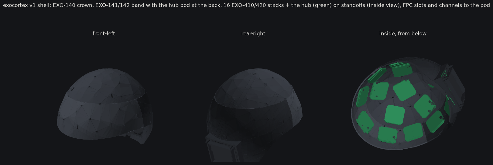
What it is
| v0 (EXO-100/101) | v1 (this) | |
|---|---|---|
| shell inner / outer face | 10.2 / 12.6 mm off the scalp | 23.2 / 25.6 mm (solved from the board stack, see below) |
| tile mount | 3 bosses, curved SLA tile on M2 × 3 inserts | 3 printed standoffs per tile at the boards' M2 holes; the flat stack screws on from the scalp side |
| hub | — | EXO-430 inside the shell at the back, REF/BIAS ball-pins on the scalp; a pod over it holds the battery |
| parts | band + crown (+ 6 tabs) | crown EXO-140, band front EXO-141, band back EXO-142 (with the pod), splice tabs EXO-143, battery cover EXO-144 |
| wiring | — | a slot behind each tile's J100, 0.8 mm channels on the outer face, into the pod through 16 slots over the hub's edge connectors |
Radial stack per tile (tile frame, measured along the tile axis from the contact board's scalp face, z_f in
out/pcb/tile_geom.json):
| thickness | source | |
|---|---|---|
| EXO-410 contact board | 1.0 | tile_geom.json pcb_t |
| DF40C-10DS + DF40C-10DP, mated | 1.5 | Hirose DF40 stacking height for the C receptacle + C header |
| EXO-420 controller board | 1.0 | |
| controller back parts, incl. the FPC connector | 2.0 | tile_geom.json back_h |
| clearance to the shell's inner face, at the worst point of the worst tile | ≥ 0.5 | measured 0.56 |
The flat boards meet the curved shell first at their corners. solve_d_si finds the smallest ellipsoid layer that
contains every tile's stack plus that clearance, which gives 23.2 mm. That is 13 mm more than v0. The ≈ 19.8 mm in
pcb.md covers only the contact board and its back parts, and the controller board adds ≈ 3.5 mm.
The board gap. Everything on the contact board's back sits in the 1.5 mm DF40 gap. The check reads every
bottom-side part from out/pcb/placement.json and compares it with its datasheet maximum height:
| part | max height (datasheet) | margin |
|---|---|---|
| UL1 TPS7A2033PDBVR, SOT-23-5 (DBV) | 1.45 | 0.05 |
| MCP6V31 / 74LVC1G17, SC70-5 | 1.10 | 0.40 |
| C0603 4.7 µF | 0.90 | 0.60 |
| ADS131M08, WQFN-32 (RSN) | 0.80 | 0.70 |
| C0402 / R0402 | 0.55 / 0.40 | ≥ 0.95 |
| C0201 / R0201 | 0.33 / 0.26 | ≥ 1.17 |
The spacers between the boards are 1.5 mm, matching the gap. No standoff enters the gap: the standoffs land on the controller's back.
Tile standoffs. There are three per tile, at the boards' M2 holes (±15.9, 0) and (0, −15.9). These come from
tile_geom.json, and the check confirms they match the routed out/pcb/EXO-420/circuit.json. Each standoff has a
Ø4.4 neck where it lands on the controller's back. That is the hole courtyard, and the nearest part (J100 at H1) sits
2.29 mm from the hole centre. Past the back parts it widens to a Ø7 body that grows out of the shell wall. The
standoffs are 6.5–7.7 mm long and different on every tile; the boards are identical.
Hub (EXO-430). It sits on the back midline, as high as it can go while its stack (board, both faces' parts and the REF/BIAS pins) stays at least 3 mm from every tile stack. That puts its centre at head z = −28.5 mm, just under T12. - Pins. The scalp face is 12.76 mm off the headform, which makes both REF and BIAS EXO-5095 (9.5 mm) pins, with the ball tip 2.5 mm off the scalp at mid-travel, the same as the tiles. - Pod. A flat board 72 mm wide cannot follow the head. Its back corners reach d ≈ 30 mm, through the 23.2 mm shell. So the shell opens over the hub into a pod: a 66 × 82 mm cavity (the board plus 5 mm all round for the FPC bends) with 2.4 mm walls and a flat ceiling at the shell's outer face. - Mounting. Four standoffs hang from the ceiling to the hub's outer face at the assumed holes (±24.5, ±32.5), each with an M2 × 6 screw from the scalp side. - Battery. The compartment for the ~60 × 50 × 8 mm pouch (62 × 52 × 9 inside) sits on the ceiling, outboard of the hub, under the EXO-144 cover (4 × M2 into inserts). The battery lead passes through the ceiling to the hub's BAT JST. - Why outboard and not below. hub.md puts the battery below the hub at the nape. Below the hub the headform is the neck: there the ellipsoid turns under, and a shell that low would not go over the head (see the donning check). So the battery rides outboard of the hub, still at the nape, still off the crown.
FPC path. Behind each tile's J100 (−16.0, 5.7), a 9 × 3 mm slot at (−16.0, 10.6) lets the FPC fold out of the
shell. From there it runs in a 9 mm wide, 0.8 mm deep channel on the outer face (covered by the beanie) to the foot of
the pod wall, climbs the wall, and drops through a ceiling slot just outside the hub's edge, beside its connector.
Ports follow hub.md: 6 top (P1–P6), 4 on each side (P7–P10 on the wearer's left, P11–P14 on the right), 2 bottom
(P15–P16). Tiles are assigned to ports by the least total FPC length, and channels that would cross the pod go round
its corners. The FPC lengths, including the climb and 40 mm slack, are 75–394 mm (T02 → P10 is the longest); per tile and port they are in
fpc_mm. The longest is past hub.md's 0.35 m skew budget (open items).
USB-C. The receptacle sits on the hub's bottom edge with the plug axis along the board, pointing down the neck. A 14 × 8 mm tunnel runs along that axis through the pod wall and the shell, and comes out on the outer face 31 mm below the board edge. The plug goes in straight from outside, under the beanie's edge. It is used only off the head, because of hub.md's interlock.
Rim. It follows v0 (z_lo − 10) except over the back, where it drops to z = −74.1 mm (flat across ±30°, then a 40° taper) to take the pod and the tunnel.
Seams. The crown seam is the plane n·p = 75.5 with n tilted 3° about y. A level cut anywhere from z = 56 to 95 goes through at least one standoff; the tilted plane cuts none. The band splits front and back at x = 0, which also misses every standoff. The pod is entirely in EXO-142. EXO-143 is 20 curved tabs, 1.2 mm thick, on the inner face across the three seams. Each tab is trimmed clear of every stack, standoff, FPC slot and the pod.
Build
uv run python -m exo.layout && uv run python -m exo.pcb.geom   # inputs: out/layout.json, out/pcb/tile_geom.json
uv run python -m exo.shell_v1             # ~3 min: STEP, STL, out/shell_v1_report.json, docs/images/shell_v1.png
uv run python -m exo.shell_v1 --slice     # + CuraEngine print time / filament per part (exo/cura.py)
uv run python -m exo.shell_v1 --render    # only re-draw the preview from out/step
The build exits non-zero if any check fails. It doesn't touch out/report.json or the v0 parts. --slice runs CuraEngine
with the Ender-3 V3 SE definition and the settings below (exo/cura.py, CURA_ROOT). Two installs work: an extracted
Cura AppImage (~/Applications/cura-extract/squashfs-root; x86-64, under qemu-user on aarch64), or, with no root and
no emulator, Ubuntu's native arm64 packages unpacked into ~/.local/opt/cura5/root:
D=~/.local/opt/cura5; mkdir -p $D/deb && cd $D/deb
P=http://ports.ubuntu.com/ubuntu-ports/pool/universe
for u in c/cura-engine/cura-engine_5.0.0-5ubuntu2_arm64.deb c/cura/cura_5.0.0-7_all.deb \
         liba/libarcus/libarcus5_5.0.0-6build2_arm64.deb libp/libpolyclipping/libpolyclipping22_6.4.2-9_arm64.deb
do curl -sfLO $P/$u; done
for f in *.deb; do dpkg -x $f $D/root; done
curl -sfL -o $D/root/usr/share/cura/resources/definitions/creality_ender3v3se.def.json \
  https://raw.githubusercontent.com/Ultimaker/Cura/5.8.0/resources/definitions/creality_ender3v3se.def.json
Cura 5.0 predates the V3 SE, hence its definition from Cura 5.8. The two engines agree within ≈ 5 % (EXO-143: 2.1 h / 9 g on the AppImage, 2.0 h / 10 g on 5.0).
Print settings (Ender-3 V3 SE, PETG, 0.4 nozzle)
| part | orientation (the STL is already oriented) | supports | est. time | est. filament |
|---|---|---|---|---|
| EXO-140 crown | split plane on the bed | tree, inside the roof and under the standoff tips | 12.3 h | 153 g |
| EXO-141 band front | upside down on the split plane | none | 4.5 h | 73 g |
| EXO-142 band back + pod | upside down on the split plane | tree, under the pod | 15.4 h | 183 g |
| EXO-143 splice tabs (20) | flat | none | 2.0 h | 10 g |
| EXO-144 battery cover | flat | none | 0.5 h | 9 g |
| total | 34.7 h | 428 g |
The first v1 (crown hub frame, no pod) was ≈ 25 h / 304 g; the pod and its supports take EXO-142 from 6.0 h / 85 g to 15.4 h / 183 g.
Settings: 0.2 mm layers, 6 walls (the 2.4 mm wall prints solid), 5 top and 5 bottom layers, 20 % infill (it only lands in the standoff bodies, the pod and the bosses), 240 °C nozzle, 80 °C bed, 60 mm/s, 40 % fan and a brim. The times are CuraEngine's with these settings. Treat them as ±20 %, because Cura's per-printer start and end sequences and acceleration limits aren't all applied by the CLI.
Assembly
Parts: - Tiles: 48 × M1.6 × 8 ISO 1207 (DIN 84) slotted cheese head, A2 (Ø3.0 head max), and 48 × Ø4 × 1.5 mm nylon spacers (M2 size, 2.2 bore). Not M2: see "Screw heads" below. - Hub: 4 × M2 × 6 ISO 7380. - Battery cover: 4 × M2 × 3 heat-set inserts (OD 3.2) and 4 × M2 × 5 button heads. - Slow epoxy for the seams. Kapton tape for the FPCs.
- Print and clean up. Remove the supports. Check that every standoff's face is flat, and sand it on a flat file if not: the face is the board's datum.
- Tap the 48 Ø1.3 tile standoff pilots with an M1.6 tap and the 4 Ø1.7 hub pilots with an M2 tap, 5–6 mm deep. A heat-set insert won't fit: Ø3.2 in the Ø4.4 neck would leave 0.6 mm of wall.
- Heat-set the 4 inserts in the battery-compartment bosses.
- Bond the shell. Glue the band front to the band back with EXO-143's band tabs, then glue the crown on with the ring tabs. Dry-fit first: the tabs are trimmed around the stacks, so they only go in one place.
- Pre-assemble each tile stack on the bench. Screw the ball-pins into the contact board's nuts. Mate EXO-410 and EXO-420 on the four DF40 pairs and plug the FPC into J100. Fit the hub's REF and BIAS EXO-5095 pins.
- Mount the hub first, from inside, on its 4 standoffs with M2 × 6 from the scalp side. Its connectors face the pod ceiling, so leave its FPC latches open.
- Mount the tiles, from the vertex down. For each tile, feed its FPC out through its slot. Seat the stack on its three standoffs with a spacer between the boards at each hole. Drive the M1.6 × 8 screws from the scalp side between the pins with a 0.4 × 2.0 slotted blade (it fits the 2.75 mm free radius between barrels). Snug only, about 0.05 N·m.
- Route the FPCs. Lay each one in its channel (port per tile in
fpc_mm) and tape it every ~40 mm. Take it over the pod wall, down through its ceiling slot, into the hub's connector, and close the latch. Do this before the battery goes in. - Battery. Plug its lead through the ceiling into the BAT JST. Lay the pouch in the compartment on a 1 mm foam pad and screw on EXO-144.
- Liner, beanie and retention dial go on as in v0. The dial slots are in the band at ±112°. The beanie cuff has to clear the USB-C tunnel mouth, or get a buttonhole there.
Checks (out/shell_v1_report.json)
- Tiles: holes against the routed board; standoff neck within the hole keep-out; shell clearance to every controller's back parts; neck wall; standoff length; thread engagement; skin past the bore under a channel; standoffs against neighbouring stacks and pin zones; stack-to-stack clearance.
- Board gap: every contact-board back-side part against the 1.5 mm gap at datasheet maximum heights, the UL1 margin, the spacer length, and standoffs kept out of the gap.
- Hub: stack against every tile stack; pod and cavity against tile standoffs and stacks; hub standoffs; REF/BIAS pin lengths; room under the ceiling; hub thread engagement; battery compartment size; USB-C tunnel open.
- Shell and print: donning (every rim point and ball tip clears the head for one fore-aft shift); channels clear of the pod; seams against standoffs; bed fit per part (convex hull, any rotation, 220 × 220 × 250); overhang area; tab count; FPC lengths.
All 34 checks pass. The ones with the least margin:
| check | value | need |
|---|---|---|
| UL1 in the 1.5 mm board gap | 0.05 mm | ≥ 0 |
| tile screw head (M1.6, Ø3.0) to the nut pads' mask openings | 0.108 mm | ≥ 0.05 |
| standoff neck in the hole keep-out | r 2.2 | ≤ 2.24 |
| shell inner face to the controllers' back parts | 0.56 mm | ≥ 0.5 |
| FPC channels clear of the pod | 0.86 mm | ≥ 0 |
| helmet goes on (worst rim point / ball tip) | 1.2 mm at a 2 mm rearward shift | ≥ 0 |
| hub stack to the nearest tile stack | 3.28 mm | ≥ 3.0 |
| EXO-141 overhang | 0.0188 of area | < 0.02 (prints without support) |
EXO-142 is reported, not checked: the pod needs tree supports (0.14 of its area overhangs), so the part prints with supports anyway; outside the pod 0.0205 of the area overhangs (0.0145 before the pod).
Open items
- UL1 has 0.05 mm in the board gap. That leaves nothing for solder fillets or a bowed board. Options: a 2.0 mm
stack (DF40HC(2.0) receptacle, raise
B2B_H;d_siand the spacers follow), a thinner LDO package (X2SON/DQN, 0.4 mm), or move UL1 to the controller. - Hub positions are assumed. M2 holes 3.5 mm in from the corners, REF/BIAS nuts at (0, ±10), and the connector
positions from hub.md's sketch. Update
HUB_HOLES,HUB_NUTS,hub_ports(),HUB_USBandHUB_BATwhen EXO-430 is placed, then rebuild. The checks recompute everything. - FPC length. The longest run (T02, 394 mm with slack) is past hub.md's 0.35 m skew budget. Options: re-check the clock skew at that length, or move the front tiles' ports to the top edge with a shorter path over the crown.
- Pod and battery thickness. The battery cover is ≈ 38 mm off the scalp at the back. hub.md's battery-below layout would be thinner, but the ellipsoid headform can't model the nape. Re-check on a scanned head.
- ESD. hub.md fits no per-port ESD because "the FPCs are inside the shell". Here they run outside the shell, under the beanie, which is still not user-accessible. Revisit if the beanie becomes removable while powered.
- Screw heads on the scalp face (resolved). Each tile mounting hole sits at the centre of a four-nut cell, 3.748 mm from every nut. An M2 button head (Ø3.5) clears the nut hex by 0.16 mm but overlaps the four nut pads (Ø4.2, exposed copper and solder) by 0.10 mm: it would short four electrodes and rock on the fillets. The tiles therefore use ISO 1207 M1.6 (Ø3.0 head max): 0.11 mm to the mask openings, checked by the build. The board holes stay Ø2.2 (the DF40s locate the boards); only the standoff pilot changes, to Ø1.3. Hub screws stay M2.
- The tile FPC exit direction. The slot assumes the cable leaves J100 toward +y. Check this against the
HC-FPC-05-10 drawing (
FPC_EXIT). - Liner and pads: the comfort-pad heights need re-deriving from the spring pins' travel, and the nape pad must clear the hub's REF/BIAS pins.
- The crown STL isn't watertight at the export tolerance; the STEP is valid. CuraEngine slices it, but repair it in another slicer if that slicer objects.
- Fit: print a coupon of the back of the shell (pod + T12) first, and check that the hub and one tile seat flat and the screws bite.