exocortex v0: mechanical architecture and design decisions
This is the visual prototype: a knitted beanie over a PETG shell lined with 16 curved tiles that carry 1,024 gold 3 mm
contacts. Nothing is electrically active. The geometry, datum scheme and routing space are laid out so that a
functional version can reuse them. Every number here comes from exo/spec.py or a generated file
in out/. Change the spec and rebuild; don't edit the outputs.
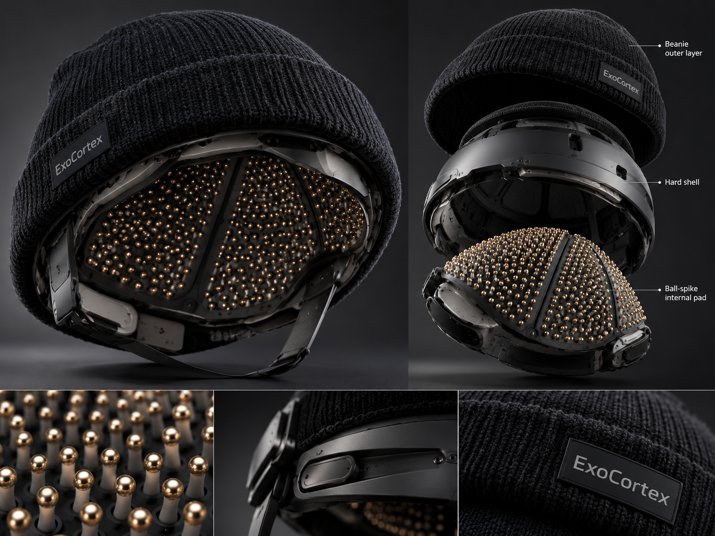
What we keep from the concept render: - gold balls sitting in light cups on tapered stems; - dark carriers; - visible seams between panels; - a plain charcoal rib-knit beanie with a woven label on the cuff.
What v0 leaves out on purpose: - The chin strap. Retention is a hidden occipital dial cradle instead. - The external temple modules. No electronics in v0. Their future place is a pod inside the rim, see §8. - The few large panels. Large panels cannot follow a doubly curved skull, so v0 uses 16 small tiles.
1. Assemblies
| assembly | part numbers | process | material |
|---|---|---|---|
| beanie (outer layer) | EXO-120 knit envelope (purchased), woven label | purchased | acrylic rib knit, charcoal |
| shell | EXO-100 band, EXO-101 crown | FDM, Ender-3 V3 SE | PETG black, 2.4 mm wall |
| liner | EXO-110 rim headband, crown pads (pucks) | purchased foam, cut | PU foam on hook-and-loop dots |
| sensor tiles | EXO-201 … EXO-216, 16 tiles × 64 contacts | SLA, one part per tile | ABS-like resin, dark grey |
| contacts | 1,024 solid brass balls Ø3.000 | purchased | H62 brass, grade 500 |
| placer (3018 tool) | PNP-100 body, PNP-101 nozzle block, PNP-102 top bridge | FDM | PETG |
| fixtures | PNP-200 tile fixture, PNP-210 ball tray, PNP-211 tray base | FDM / diode laser | PETG / 3 mm black cast acrylic |
| coupons, forming | EXO-300, EXO-301, EXO-310, EXO-311, EXO-320 | SLA / FDM / MDF | see §5 |
2. Corrected dimensions
The spec's numbers do not all fit together. Here are the corrections; each one is computed in exo/head.py and
exo/layout.py.
| item | spec | v0 | why |
|---|---|---|---|
| contact pitch | 7.5 mm | 5.30 mm (optimum 5.302, rounded down to 0.05) | See below. |
| tile size | ~60 × 60 mm | 44.2 mm, corners chamfered 6 mm | Edge = 7 × pitch + Ø3.9 cup + 2 × 1.6 mm margin. |
| coupon pitch | 8 mm | the tile pitch | A coupon only tells you something if it uses the production pitch. |
| contacts | ~1,024 | 1,024 (16 × 8 × 8) | Count kept; the pitch is what changed. |
| shell wall | 1.8–2.5 mm | 2.4 mm | Six 0.4 mm perimeters, and it has to hold an M2 × 3 insert with 0.6 mm of skin outside it. |
| protrusion | 3–5 mm | 5.0 mm | Leaves a 1.5 mm stem under the cup. |
Why the pitch had to change. The tiles can only cover the scalp above the forehead cuff line (z = 15 mm), 22 mm above the ears and down to the occiput (z = −10 mm). On the 57 cm headform that area is 48,200 mm². At 7.5 mm pitch, 1,024 contacts need 1,024 × 7.5² = 57,600 mm², before allowing any gap between tiles or for square tiles not tiling a dome. So 7.5 mm is impossible.
The layout optimiser places 16 tiles of 8 × 8 contacts with a 3 mm minimum gap between them. The largest pitch it finds is 5.18 mm, which v0 rounds down to 5.30 mm.
Radial stack
Each layer is the headform ellipsoid (a 100, b 80, c 102 mm) grown by d on every semi-axis. These grown layers differ from true normal offsets by less than 0.1 mm at d = 15.
| d (mm) | layer | circumference at the reference plane |
|---|---|---|
| 0 | headform: scalp over hair (measure the wearer) | 567 mm |
| 2.5 | ball tips in wear mode | 583 mm |
| 4.0 | ball centres | |
| 7.5 | tile carrier, inner (post) face | |
| 8.7 | tile carrier, back face | |
| 9.0 | datum plane through the three feet | |
| 10.2 | shell inner face (1.5 mm mount gap) | |
| 12.6 | shell outer face | 646 mm |
| 15.1 | beanie outer face | 662 mm |
A beanie on a bare head is about 583 mm around the outside. Over exocortex it is 662 mm, which is 14 % bigger: it reads as a thick winter beanie, not a helmet. A one-size rib beanie stretches to 64–66 cm without the knit opening up. The 15 mm stack is the cost of keeping the balls 2.5 mm off the scalp.
Mass estimate
| item | g |
|---|---|
| 1,024 brass balls (0.12 g each) | 123 |
| shell (PETG) | 207 |
| 16 tiles (resin) | 61 |
| beanie | ~85 |
| foam, fasteners, inserts, dial | ~45 |
| total | 513 |
That is roughly one and a half bicycle helmets, fine for demos. The shell is the heaviest item, then the brass. Swapping to gold-plated ABS no-hole beads would save about 110 g, at the cost of size consistency and a less metallic look. See §4.
3. Tile count and layout
Tiles are placed in rings around the vertex. Each ring follows θ(φ) = θ0 + θ1 cos φ + θ2 cos 2φ and spaces its tiles equally by arc length. A ring's phase is either 0 (a tile on the midline) or ½ (a gap on the midline), so every layout is left/right symmetric. Every tile's "up" edge points at the vertex.
The optimiser (differential evolution over the ring parameters) maximises the pitch subject to two constraints: - no two tiles come closer than 3 mm on the surface; - no tile reaches below z_lo(φ).
Ring arrangements tried for 16 tiles
| rings (tiles per ring) | max pitch (mm) |
|---|---|
| 1 + 5 + 10 | 5.18 |
| 1 + 6 + 9 | 4.96 |
| 4 + 12 | 4.48 |
| 2 + 6 + 8 | 4.26 |
Tile-count study (uv run python -m exo.layout --study → out/tile_study.json)
| tiles | grid | contacts | pitch (mm) | coverage | max post tilt | max flat-sheet strain | screws | FPC tails |
|---|---|---|---|---|---|---|---|---|
| 10 | 10 × 10 | 1,000 | 5.10 | 58% | 25.8° | 3.0 % | 20 | 10 × 100 lines |
| 12 | 9 × 9 | 972 | 5.15 | 57% | 23.9° | 2.4 % | 24 | 12 × 81 |
| 16 | 8 × 8 | 1,024 | 5.30 | 63% | 24.9° | 2.0 % | 32 | 16 × 64 |
| 20 | 7 × 7 | 980 | 4.80 | 50% | 17.6° | 1.2 % | 40 | 20 × 49 |
Why 16 tiles of 8 × 8: - It is the only option that reaches 1,024 contacts. - 64 lines fit two standard 0.5 mm-pitch 40-way FPC tails, with 16 spare lines for reference and shield. - One tile is one SLA print of about 45 mm, two to a plate. - One tile is 64 placements, about 12 minutes on the CNC.
Fewer, larger tiles curve more (deeper parts, more post tilt, more forming strain). More, smaller tiles waste more area in gaps and double the screws and connectors.
4. Contact: snap cup + solid brass ball
Decision. Each tile's carrier, its 64 tapered stems and their snap cups are one SLA part, printed at its final curvature (EXO-2xx). A solid Ø3 mm brass ball is pressed into each cup by the 3018 placer.
Cup geometry: - the lip sits 0.30 mm above the ball's equator; - that gives a mouth of Ø2.939, i.e. 0.061 mm of diametral interference; - the coupon ladder (EXO-300/301) fixes the final value.
A drop of the same resin wicked into each cup and UV-cured is the secondary retention, the spec's "adhesive as backup". No part is glued by hand.
Options compared (spec §5)
| A: beads on printed stems | B: beads on bought pins | C: monolithic SLA ball + stem, painted | D: integrated posts, place beads | chosen: SLA cups + solid brass balls | |
|---|---|---|---|---|---|
| unit cost (1,024) | ~$0.01 | ~$0.02 | resin only | ~$0.01 | ~$0.07 (balls) + resin |
| appearance | hole visible on random beads | same | paint wears, no metal lustre | hole visible | real metal, no holes |
| consistency | bead hole ±0.1 | pin length varies | ±0.05 (SLA) | bead ±0.1 | ball ±0.0125 (grade 500), cup ±0.05 |
| insertion | 1,024 stems plus 1,024 beads, each oriented | same | none, but painting 1,024 spheres | 1,024 beads, hole must face the post | 1,024 balls, no orientation |
| retention | glue | glue | monolithic | press + glue | snap + resin wick |
| scales to | manual | manual | SLA throughput | needs bead orientation | vacuum pick-and-place, or a gang press later |
Why beads with holes lose. A bead picked out of a tray lands with its hole pointing anywhere. Pressing it onto a post needs the hole aligned, which means a vision system or a vibratory orienter. A solid sphere has no orientation. On top of that, any bead whose hole faces the scalp shows a dark pit in macro shots.
Why brass: - it is solid, so there is nothing to orient; - it has real metallic lustre; - it is conductive; - it can later be gold- or Ag/AgCl-plated, so a functional tile can keep the same ball and cup; - grade-500 balls hold Ø ±0.0125 mm.
Spec options set aside: - Rods inserted into a thermoformed sheet: needs 1,024 separate stems and a forming step (§5). - Painted SLA balls: paint wears.
5. Fabrication order
| pathway | sequence | verdict for v0 |
|---|---|---|
| A: insert, then form | flat carrier → CNC inserts rods → heat and form | Rejected. Adhesive softens near 130 °C. Posts tilt with the local surface, and hole centres move by up to ~0.4 mm. The studs foul the mould. |
| B: form, then insert | flat drilled carrier → form → insert along 3D axes | Workable, but the formed hole positions have to be measured and the holes tilt up to the surface slope. Needs a per-tile curved fixture. |
| C: form carrier, attach a flexible array | formed carrier + separately made flexible contact sheet | This is the v1 route for electrical routing (a kirigami/comb FPC). Not needed for v0. |
| v0: print at final curvature | SLA tile with posts → CNC presses balls along +z | Chosen. No forming, no stems, no adhesive in the loop. Coordinates come straight from CAD. |
One pull direction. All 64 posts on a tile are parallel to the tile axis w, which is the normal of the plane through its three feet. That single axis lets three processes share one direction: - the SLA prints the tile with every post vertical; - a 3-axis CNC presses every ball along machine Z; - a future injection mould opens in one direction.
The cost is that a post's axis is not the local scalp normal. At the tile corners the gap is up to 24.9° (T-corner worst case; median tile ≈ 20°), invisible at 3 mm. Because the post lengths follow the surface, the ball centres still sit on the d = 4.0 layer to within 0.1 mm.
Thermoforming still matters for v1. Copper on polyimide can't be formed, so any planar-patterned interconnect needs either a developable (comb) layout or a formed substrate. A flat sheet draped onto a surface of Gaussian curvature K has to strain in-plane. For a tile of half-diagonal ρ:
ε ≈ K ρ² / 6 hole shift ≈ K ρ³ / 6
For the 44 mm tile (ρ ≈ 27.0 mm) on a 95 mm Gaussian radius: ε ≈ 1.4 % and hole shift ≈ 0.40 mm. Those are fine for
PETG and fatal for rolled copper. Per-tile values are in out/layout.json → metrics.flat_sheet_strain_pct and
hole_shift_flat_to_formed_mm. Worst case: 1.98 % strain and 0.53 mm hole shift (T01, the vertex tile, Gaussian radius 78 mm).
The A-vs-B coupon experiment stays in the milestone (build.md T6). Its job is to measure these numbers for v1, not to gate v0.
6. Carrier materials
| material | forming | dimensional | cracking at holes | adhesive | skin contact | laser | verdict |
|---|---|---|---|---|---|---|---|
| PETG sheet 1.0 mm | 120–140 °C, easy, no pre-dry | good, low springback | good | CA/epoxy OK | widely used in medical packaging | don't: melts and strings; drill or print it | Thermoforming coupons (EXO-310) |
| ABS sheet | 140–160 °C | good | fair | good | depends on grade | don't: dense soot and styrene fumes | — |
| PC sheet | 170–190 °C, must pre-dry | excellent | good | fair | good grades exist | don't: chars, poor cut, toxic fumes | v1 candidate (heat resistance) |
| PP sheet | narrow window, high springback | poor | excellent | poor (low surface energy) | good | melts | — |
| ABS-like SLA resin | n/a (printed curved) | ±0.05 mm | fair: needs the 0.3–0.4 mm cup walls | the same resin as wick | not certified; liner isolates it | n/a | v0 tiles |
| tough / flexible-blend SLA resin | n/a | ±0.05 mm | good | same | not certified | n/a | Fallback if cups crack on the coupon. |
Laser rules for the shop (a diode engraver): - Never cut PVC or vinyl. It releases HCl and corrodes the machine. - No PC or ABS. - PETG melts instead of cutting. - A 450 nm diode does not cut clear acrylic, so the ball tray (PNP-210) is black cast acrylic. - Faux leather is usually PVC/PU, so the label is woven, not lasered. - Run fume extraction for every cut.
7. Datum scheme and tile mounting
Every tile has three 5 mm feet on its back, at cell centres between posts, at the same cells on every tile: - A, round hole, at cell (−3, −3); - B, slot along A–B, at cell (+3, −3); - C, plain support foot, at cell (0, +3).
The feet end on one plane, the datum plane, 0.3 mm behind the carrier at the feet (d = 9.0). The tile frame is defined from it: w is the plane's normal and the origin lies on the plane. On a dome the tile's centre bulges about 1.5 mm past the plane of its feet, so nothing flat may touch the tile between its feet.
| use | how the datum is used |
|---|---|
| CNC fixture PNP-200 | A pocketed plate: three pads at A, B, C end on the datum plane; the tile's back hangs over a 5 mm pocket. Ø2 dowels go into A and slot B. The feet are identical on every tile, so one fixture holds all 16 tiles. The Ø1.8 XY zero hole is at tile (−40, 0), off the tile. |
| shell | Each tile has three PETG bosses on the shell's inner face, ending on the datum plane. A and B take M2 × 3 heat-set inserts (Ø3.2 hole, 3.0 deep, ≥ 0.6 mm skin left outside, checked in report.json). C is a plain support. |
| keying | Separate from the feet: a Ø1.5 key pin on the shell at a tile-specific cell (16 different cells, spec.key_cells) enters a Ø1.8 key hole that only the right tile has. The wrong tile, or a tile turned 180°, lands its carrier back on the pin and stands ~0.8 mm proud, so the mistake is visible and the screws can't pull it down. |
| fastening | 2 × M2 × 4 button-head screws from the post side, through A and B. The 1.3 mm hex key fits between the cups. A tile comes out from inside without touching the rest. |
8. Shell (EXO-100, EXO-101)
The shell is split at z = 70 into two parts:
- EXO-100 band, from z = 70 down to the rim. It prints upside down on the split plane with no supports: every
wall there is within 45° of vertical, which report.json checks.
- EXO-101 crown, the cap above z = 70. It prints on its split plane; the roof inside needs Cura tree supports.
The marks are hidden behind the tiles.
Both parts fit the 220 × 220 bed diagonally.
Joints and openings: - Band–crown joint: a 1.2 mm tongue on the band, 6 mm long, inside the crown, bonded with two-part epoxy. The tongue is cut back around the crown's bosses. - Rim: follows z_lo(φ) − 10 mm. That zone carries the headband and the dial slots. - Vents: about 40 Ø3.5 holes at points in the inter-tile gaps. Air goes scalp → tile vent holes (Ø1.4 at every free cell) → mount gap → shell vents → knit. - Retention: two 12 × 2.5 slots behind the ears hold the clips of a purchased bike-helmet dial cradle, hidden under the beanie cuff. - FPC passages: the 1.5 mm mount gap runs continuously to the rim. Every tile's back has simulated routing (0.6 × 0.3 mm grooves under each row into a bus) and a 22 mm tail land on its −x (rim-side) edge. - Future electronics pod: sits inside the occipital rim zone. Its bosses are added when the pod exists.
Fasteners evaluated
| method | tiles | shell joint | textile | notes |
|---|---|---|---|---|
| M2 screw + heat-set insert | chosen | — | — | Reversible, precise, cheap. 32 screws. |
| snap fit | rejected | — | — | SLA snaps creep and crack; serviceability falls after a few cycles. |
| magnets | rejected | — | — | Steel/NdFeB near future EEG sensing is a no-go: motion artefacts and magnetic interference. Mass too. |
| hook-and-loop | — | — | pads, headband | Quick to remove for photo mode. |
| epoxy | — | chosen | — | Shell halves don't need servicing. |
| elastic stretch | — | — | beanie | The beanie stretches over the shell; a 10 mm cuff fold hides the rim. |
9. Safety and ergonomics
Wear mode. The head rests on foam, never on the array:
- EXO-110 rim headband: 8 mm soft PU foam on hook-and-loop, round the forehead, temples and occiput.
- Crown pads: up to 8 foam pucks, Ø ≤ 16 mm, in the largest gaps where tiles meet. layout.json → pads.
The pads fill the 10.2 mm from the shell's inner face to the scalp. Starting from ~12 mm free height they compress about 15 % at fit. Reaching a ball tip (d = 2.5) would need about 75 % compression, which a soft PU foam only reaches under several times head weight. So the tips stay 2.5 mm off the scalp under normal wear and a hand pressing on top.
Photo mode. Peel off the pads and headband. The array is fully exposed for inverted and macro shots.
Retention of the balls: - the snap cup (pull-out target ≥ 1.5 N, tested on the coupon); - a UV-cured resin wick in every cup; - a 100 % tug check after placement (build.md T4).
A ball weighs 1.2 mN, so 1.5 N is a margin of more than 1,000×.
Skin contact. In wear mode nothing rigid touches the scalp. Neither ABS-like resin nor raw brass is a skin-contact material, and the pads keep them off the skin. A functional v1 is a separate problem: - compliant spring pins with a defined force (~0.5–1 N per contact); - gold or Ag/AgCl contact surfaces; - ISO 10993-tested contact materials; - its own validation.
Edges. The shell rim is filleted and covered by the headband foam. The beanie covers every outer edge.