Scroll to take it apart
Every part, every file.
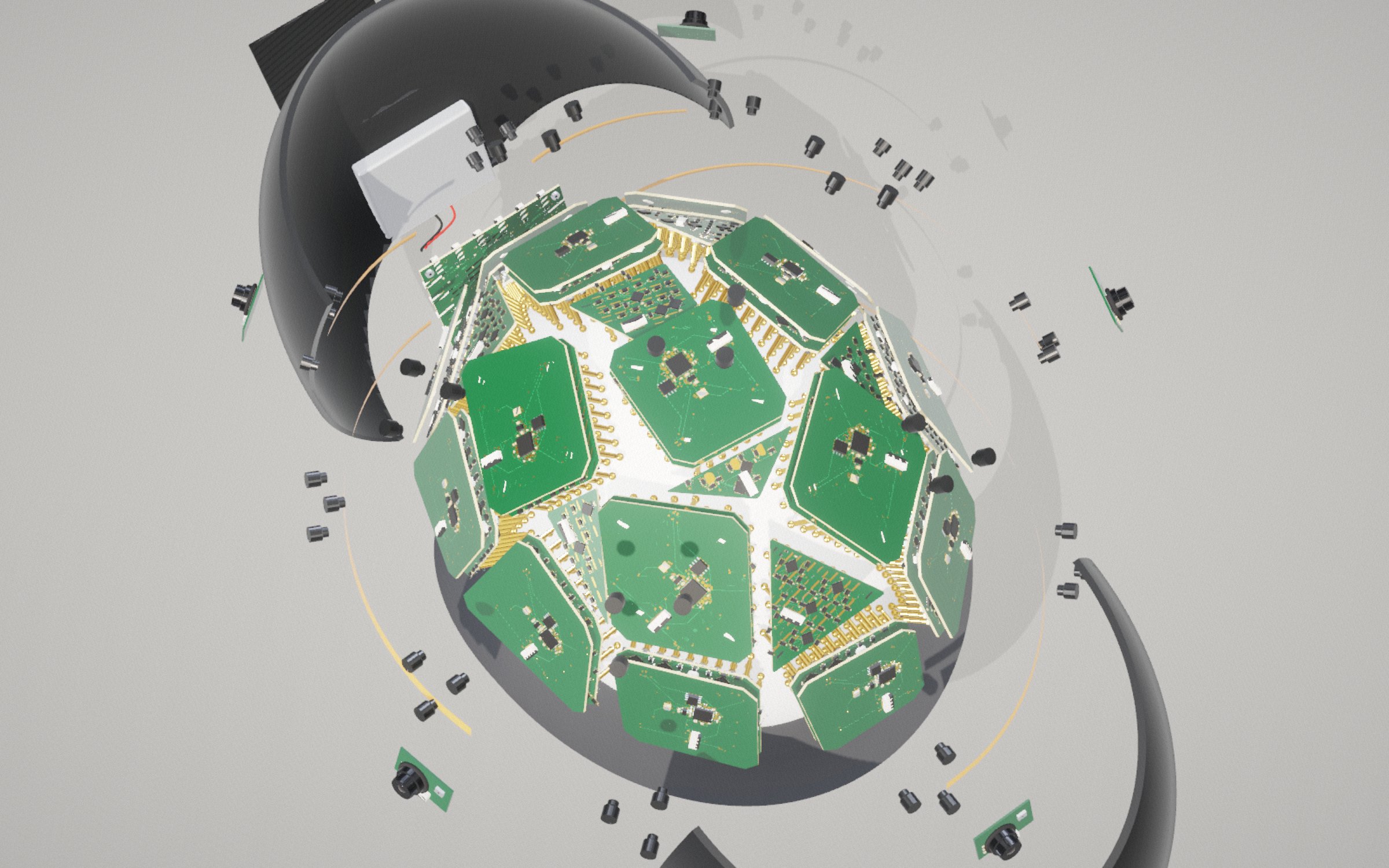
25 boards, no two alike. Trapezoids and triangles cut to the head, a printed shell, five cameras, and a knit beanie over all of it.
1,490dry gold contacts, no gel
95.9%of the scalp under a board
25contact boards, every one a different shape
5cameras, 72° apart
35 hto print the shell
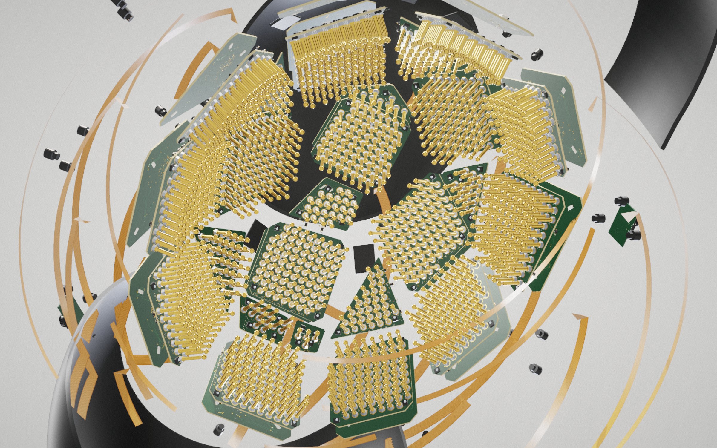
1,490 contacts. All of them gold.
Seen from the scalp: every board's ball-pins, six lengths so each one reaches.
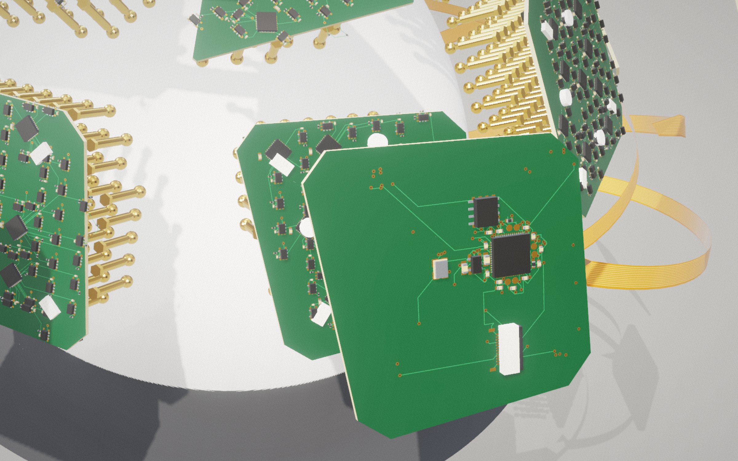
Real boards, real parts.
A buffer behind every pin, an ADS131M08 for every eight, an RP2040 controller stacked 1.5 mm behind on four DF40 pairs.
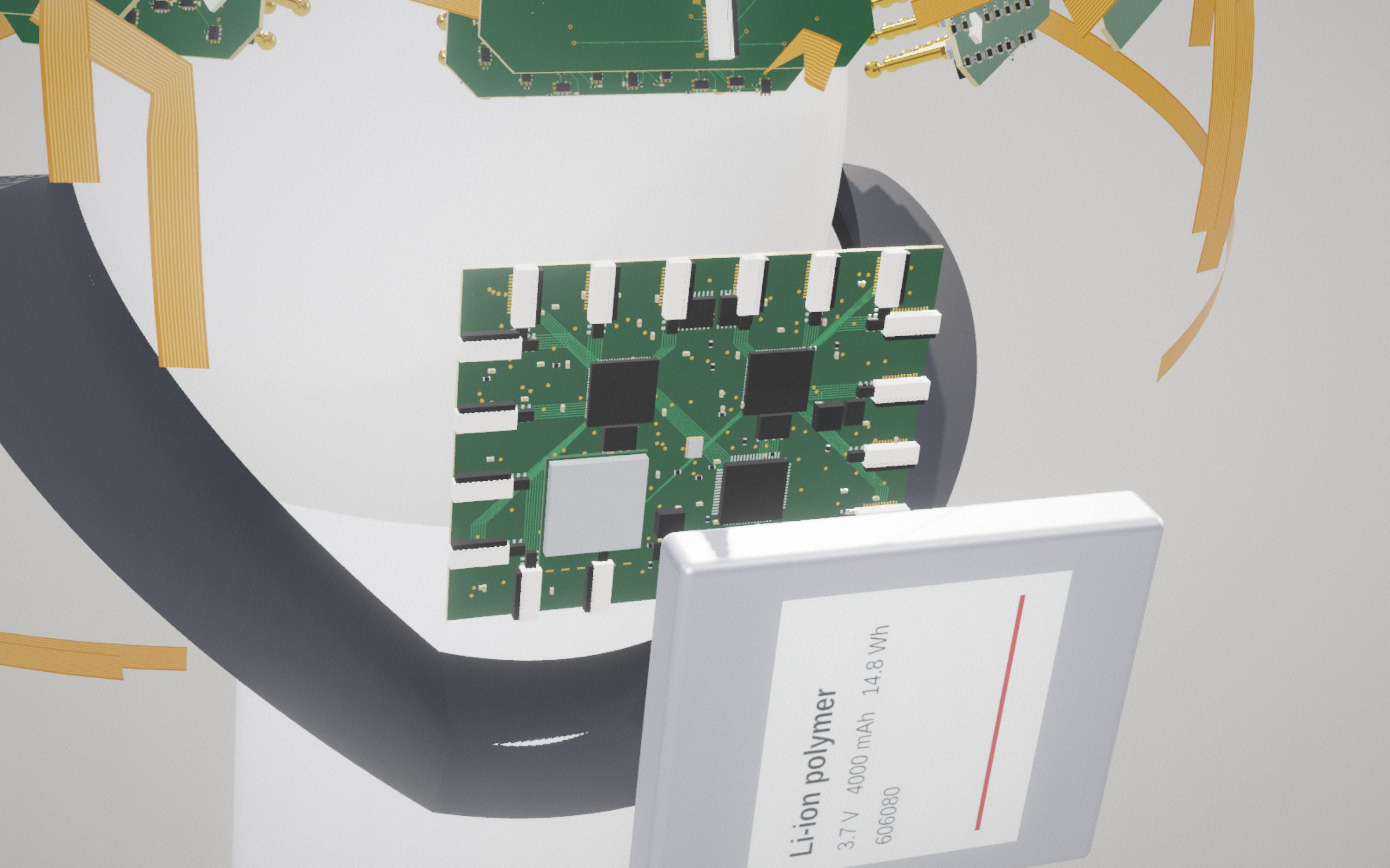
The hub.
Sixteen cable ports, two RP2350s, an ESP32-S3 for Wi-Fi, USB 2.0 through an FT2232H, and a 4000 mAh cell under the pod cover.
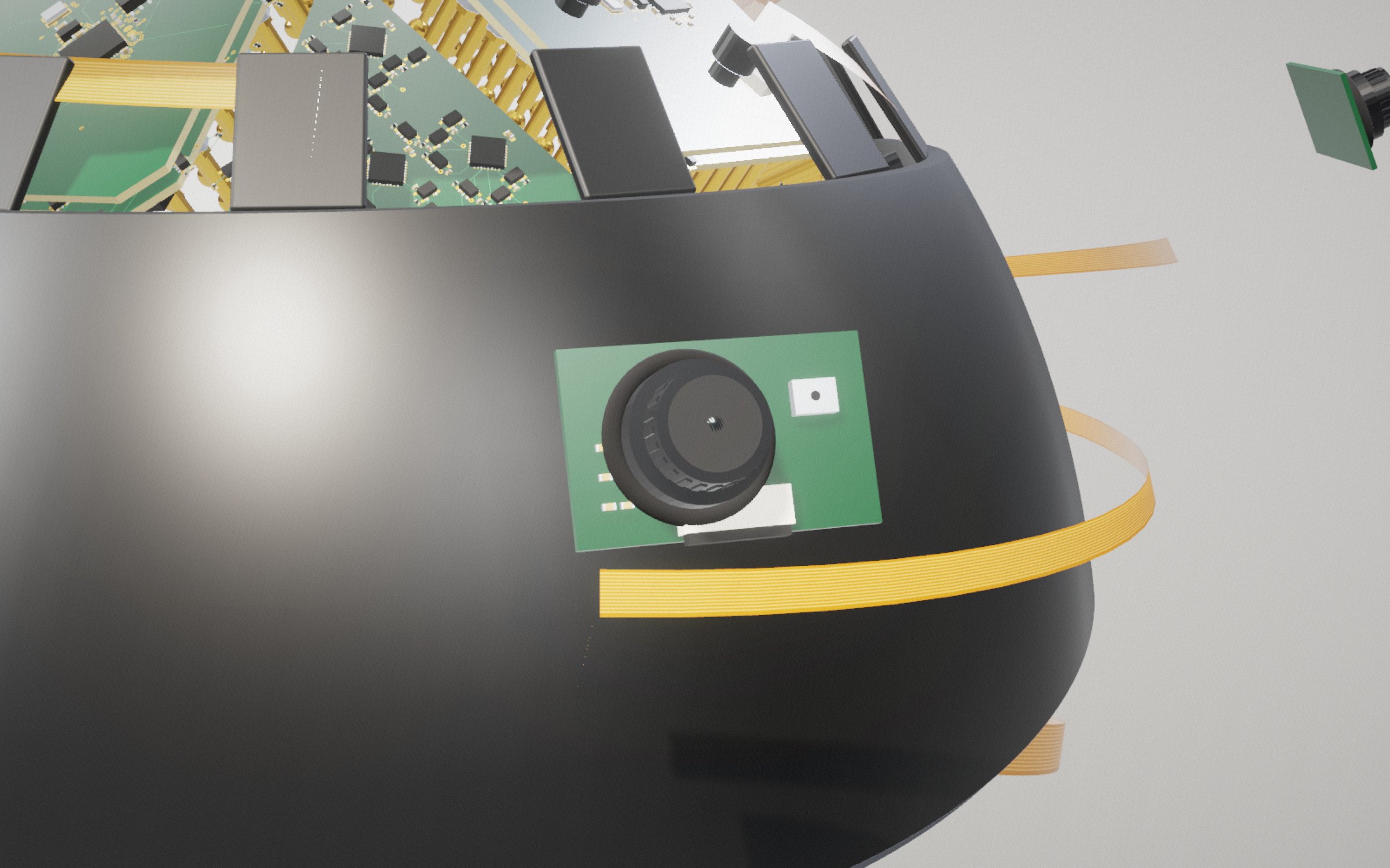
Five cameras.
72° apart around the band, each lens through the knit with a microphone beside it.
Everything to build one.
Bill of materialsAbout $1,600–1,900 for a two-tile bench order
Plans and files3D parts, board files, pin drawings
Design notesHow and why it is built this way
Where it stands
The v1 boards in the order files are the routed squares; the shapes above are the v2 layout study. Nothing has been built yet.
| part | what it is | state | |
|---|---|---|---|
| EXO-420 controller board | RP2040, flash, crystal, LDO, FPC to the hub. 6-layer, 1.0 mm | routed: 131 traces, 112 vias, 0 DRC errors | ready |
| EXO-410 contact board | 60 ball-pin nuts, 62 followers, 8 × ADS131M08, 4 optical sensors. 6-layer HDI | routing in progress: best run has 4 open nets, no shorts | in progress |
| Shell EXO-140…144 | PETG on an Ender-3 V3 SE | 34/34 design checks pass | printable |
| Ball-pins EXO-5075…5125 | custom gold spring pins, six lengths | CAD and drawings; RFQ drafted | quote needed |
| Hub EXO-430 | reference and bias, clock, 16 tile ports, battery, USB-C and Wi-Fi | circuit and BOM; no layout yet | in design |
| Camera ring | five cameras and microphones, 72° apart around the band | concept only | planned |